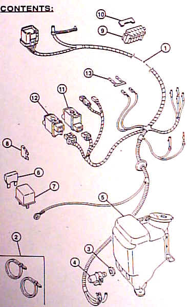
HARDTOP WIRING KIT
JEEP WRANGLER TJ

Installation Instructions


Read entire instructions thoroughly before starting.  References to the service manual wiring diagrams and operation sections will be required for adjustments, fastener torques, and troubleshooting.

Note:   These instructions were manually copied from digital images of the original instructions.  Please review to be sure that they make sense before following them - there could be errors... 

Paul M. Provencher
http://4x4icon.com

TOOLS REQUIRED:

· A selection of phillips head screwdrivers  · 15mm socket  · 10mm socket  · Modeler's knife
· Solder  · Electrical Tape  · A selection of flat head screw drivers

Item Qty. Description
1 1 Hardtop Wiring Assembly
2 12 Tie Straps
3 1 Grommet
4 1 Rear Window Washer Pump
5 1 Reservoir
6 1 Maxi Fuse
7 1 EBL Relay
8 1 Mini Fuse
9 1 Red 10-way Connector
10 1 Yellow Locking Wedge
11 1 EBL Switch
12 1 Rear Wipe Switch
13 2 Terminals
14 1 Instruction Sheet

NOTE:

This harness carries the same colors and wire functions as the O.E. harness.


K6858210                                                 09/04/98                                                                                        Page 1 of 8


  1. Find existing 10-way connector and rear washer supply hose located at the driver's side rear hardtop pillar.  Plug in the corresponding connections from the hardtop overlay harness (Item 1).
  2. Route the harness forward and tuck in-between the existing harness and the body sheet metal.
  1. Carefully remove the wire harness down and in-between the sport bar and the body sheet metal.
  2. Route the hardtop overlay harness down and in-between the sport bar and the body sheet metal.
  3. Using tie straps (Item 2), secure the overlay harness to the existing body harness.
  4. Re-install the wire harness protector panel.
  1. Continue routing the overlay harness forward and under the driver's door sill.
  2. Locate unused round grommet directly below the main bulkhead wiring grommet and remove it by pushing in from the engine compartment side.  Discard the grommet.
  3. Route the round eyelet and washer reservoir connections from the overlay harness forward thru the bulkhead and seat the in-line grommet.
 

K6858210                                              09/04/98                                                                                           Page 2 of 8


  1. Disconnect negative battery cable and isolate.
  2. Using a 15mm socket, install ground eyelet from the overlay harness to the existing ground located on the driver's side of the upper bulkhead.
  1. Using a 10mm socket, unscrew three bolts to remove the existing windshield washer reservoir.  Discard the reservoir.
  2. Sub-assemble the supplied grommet (Item 3) and rear window washer pump (Item 4) to the new reservoir (Item 5).
  3. Sub-assemble the retained gromment, windshield washer pump, lid, and fluid to the new reservoir.
  4. Using the three existing bolts, install the new reservoir assembly to the vehicle.
  1. Plug-in 2-way connector and supply hose from the overlay harness to the corresponding connections on the rear window washer pump.
  2. Re-install the existing 2-way connector and supply hose to the windshield washer pump.
  3. Using tie straps, secure the overlay harness to the existing engine harness.
 

K6858210                                            09/04/98                                                                                           Page 3 of 8


wpe1.jpg (17570 bytes)

  1. Remove the cover from the power distribution center.
  2. Install maxi fuse (Item 6) to the F15 location if the PDC.  The location is shown on the PDC cover.
  3. Install EBL Relay (Item 7) to the heated rear window location of the PDC.
  4. Install mini fuse (Item 8) to the cavity #17 of the fuse panel (located behind the glove box).
NOTE:

Most vehicles will have a fuse already installed.  If so, disregard step #23.

wpe2.jpg (17260 bytes)

  1. Pry up to remove the I/P top cover.
  2. Remove the ash receiver and unscrew three phillips head screws to remove the I/P center bezel.
wpe3.jpg (15875 bytes)
  1. Unscrew four phillips head screws from the cigar lighter/switch plate.  Pull out and let hang.
  2. Unscrew four phillips head screws from the HVAC control plate.  Pull out and let hang.
 

K6858210                                             09/04/98                                                                                           Page 4 of 8


wpe4.jpg (18640 bytes)
  1. Unscrew five phillips head screws to remove the I/P cluster bezel.
  2. Unscrew a total of four phillips head screws to remove the I/P cluster.
  3. Unscrew a total of four phillips head screws to remove the knee blocker trim panel and knee blocker.
wpe5.jpg (16507 bytes)
  1. Find the 100-way connector located under the I/P and bolted to the LH body panel support.  Disconnect the red 10-way connector from the bottom cavity.  Remove the connector's yellow locking wedge.
NOTE:

If there is no existing 10-way connector to be found, use the connector (Item 9) and locking wedge (Item 10) supplied in the kit.


wpe6.jpg (14661 bytes)
  1. Insert four terminaled wires from the overlay harness into either the existing or supplied connector as shown in the illustration to the left.


NOTE:

Some models will have existing pink/white and yellow wires in the 10-way connector.  The corresponding wires from the overlay harness must be center spliced onto these existing wires.   Solder the splices and wrap with electrical tape to prevent shorts.

  1. Install the yellow locking wedge and plug the 10-way connector into the 100-way connector.
 

K6858210                                          09/04/98                                                                                           Page 5 of 8


wpe7.jpg (19031 bytes)
NOTE:

Steps 34 - 36 apply to 1997 models only.

  1. Disconnect grey 12-way connector from the top cavity of the 100-way connector.  Remove the 12-way connector's red locking wedge.
  2. Insert the blue/white round type terminaled wire from the overlay harness into cavity #9 of the connector.  Cut off unused blue/white blade type terminaled wire and insulate.  The connector is numbered for location.
  3. Re-install red locking wedge and plug the 12-way connector back into the 100-way connector.
wpe8.jpg (18032 bytes)
NOTE:

Steps 34a - 36a apply to 1998 models only.

  1. a.  Locate and unplug grey 6-way connector under the I/P and near the 100-way connector.
  2. a.  You will notice that there is a blue/white wire on only one side of this connector.  Remove the locking wedge, and insert the blue/white wire with blade terminal, into cavity #2 of the connector.   Cut-off the unused blue/white round type terminaled wire and insulate the cut.
  3. a.  Re-install locking wedge and plug-in connectors.
wpe9.jpg (17600 bytes)
NOTE:

Steps 34c - 36c apply to 1999 models only.

  1. c.  Locate grey 10-way connector under the I/P and near the top of the 100-way connector.
  2. c.  Cut blue/white wire free of the 10-way connector and cut round type terminal off the blue/white wire from the overlay harness.  Splice these two blue/white wires together, then solder and insulate the spice.
  3. c.  Cut-off the unused blue/white blade type terminaled wire and insulate cut.
 

K6858210                                                09/04/98                                                                                      Page 6 of 8


wpeA.jpg (17069 bytes)
  1. Route the four switch connectors from the overlay harness inside of the I/P to the switch and HVAC plates.
  2. Remove the two block-off plugs from the switch plate and install the EBL switch (Item 11) and rear wipe switch (Item 12)
  3. Plug-in the 6-way and 4-way connectors from the overlay harness into the switches.
wpeB.jpg (17829 bytes)
  1. Unplug black 2-way connector from the HVAC control.  Plug the two black 2-way connectors from the overlay harness in-between.


  1. Remove the RH (passenger side) 10-way I/P cluster connector by squeezing in on the tabs and sliding down off of the I/P bracket.
wpeC.jpg (17066 bytes)
  1. Remove approximately 3" of tape from the connector harness.  Disengage the red locking wedge by pulling it partially out the back of the connector (wire side).
  2. Insert Lt. blue/white and Dk. blue/Lt. green terminaled wires from the overlay harness into the connector as shown in the illustration at left.
NOTE:

On '97 models, replace these two terminals with the loose terminals (Item 13) supplied in the kit.  Solder these connections!

  1. Re-install connector to the I/P bracket and re-install the I/P cluster.


K6858210                                                09/04/98                                                                                      Page 7 of 8


wpeD.jpg (13772 bytes)

Using tie straps, secure the overlay harness to the existing I/P harness.  Be sure there is no interference with any moving parts.

Re-connect the negative battery cable and check for proper operation of the rear window wiper/washer, defroster, and dome lamp.

Re-install the HVAC and cigar lighter/switch plates, the knee blocker trim panel, I/P cluster bezel, I/P center bezel, ash receiver, and I/P top cover.

NOTE:

This harness carries the same colors and wire functions as the O.E. harness.


K6858210                                                09/04/98                                                                                      Page 8 of 8