![]()
|
My friend Dave and I talked at length about my Jeep. He eventually decided he'd like to have one as a second vehicle. He located a nice TJ and showed up at work one day all smiles. Not long after that, he started going over different accessories and modifications that he was considering. I think it's safe to say that Dave has the Jeep disease. I am not sure if he caught it from me, or if it lie dormant for years. But regardless of the source, I felt it my duty to help him embrace it. Along the way, the topic of shocks came up. I don't remember the exact conversation, but Dave indicated that he wanted to improve the ride of the Jeep and had found the Rancho Shock system. He wanted to know what I thought. I don't usually have any problem giving my opinion but had to admit, at least to myself, that I didn't know very much about Rancho's shocks. What I did know was useless. That is to say, I harbored a 30-year old impression of rusty old Ford and Chevy pick-up trucks with noisy, jacked up leaf springs. Plastered all over the shocks and often the rest of the vehicles, was the Rancho name. Let's just say that comparing my brand recognition experience with other brands, like Bilstein or KYB, it left me thinking that Rancho was not a very distinguished trademark. But I try to be fair. So I dug back into the research I had been doing about suspension systems. My friend Roscoe and a couple people installed Rancho lift kits. The prevailing opinion of those folks was that the lift kits were well designed, offered great value for the money, and came with everything needed to install a well-engineered suspension system. The resulting performance is also very good. So I updated my view of Rancho to allow for the possibility that my recollection of their products was out of date and ignorant. I took another look at their shock absorber systems. I found that the products are in widespread use, appear to be well regarded, and while somewhat expensive, appear to perform as represented. |
|
|
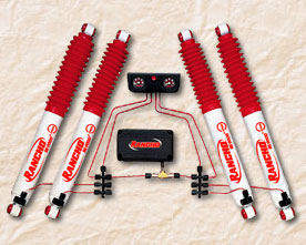
So with all this churning, I felt that Dave was probably looking in the right direction with his desire to improve the shocks on his TJ. I don't think I specifically recommended a solution. He came in my office a few days later to tell me that he had purchased the Rancho® Dual-action Remote Control System, Part No. RS9700 that includes the 5-position shocks, the remote control system that consists of a small air compressor, air lines, and a head unit. Wow. The concept looked pretty cool. It sounds like a long way to go for a cup of coffee, but anyone who has climbed under a muddy 4x4 will tell you, fumbling around to adjust a knob on four shocks is probably not high on anyone's list of things to do. So if you want to have adjustable shocks, the remote control sure sounds like the way to go. |
 |
 |
I agreed to help Dave install this wondrous collection of devices. I was very curious about it, and thought it would be a great way to get up close and personal with it since I too am considering shock options. It was a few weeks before our schedules coincided but finally the day came when we could set about putting it together. I felt confident about removing and replacing the shocks as I have done it once on the TJ and countless times on other vehicles. I was less confident about the remote control system but reasoned it would not be any different than installing a high-end stereo system, or perhaps running a complete set of brake lines, both jobs that I have done on numerous occasions. |
|
Remote Control Location and Installation |
|
|
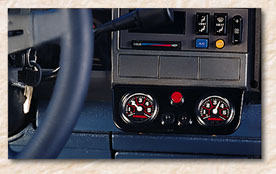
There were some problems that had to be worked out before we could really get started. The TJ has limited places where the remote control panel can be installed. Some people have chosen to cut holes in their console or dash and install the gauges and switches that way. We looked at some of these options but concluded that it was not a great solution for Dave. In the end, Dave decided that he'd like the remote control unit up on the coin tray where he could touch and see it easily. I am inclined to agree even though that created some new problems. Mainly the issue is that the bracket supplied is intended for under-dash applications. As such, the lines running to the remote are exposed, looking a little like the back of a really small stereo. We also had to use a couple of grommets to raise the bracket so the buttons and inputs would clear the recess of the coin tray. |
 |
|
Once these issues were worked out, I removed the fascia panel surrounding the radio, heater and ash tray. This involved the removal of a vent cover on the dash - just snapped it out carefully, and the removal of three screws that held the fascia in place. It is a little tricky to pry it forward around the radio, etc., but it came right out. I measured the location of the mounting holes and drilled them out, centering the bracket front and rear, and side to side. This leaves enough room to get the inputs hooked up in the back and enough room in front to operate the controls. |
|
|
I assembled the remote control components onto the bracket. There are two pressure gauges, one power button for the compressor, and two pressure-release buttons, one for front and rear. This assembly was straightforward. The pressure-release buttons are a bit quirky and required some thinking to prevent marking them up. |
|
|
Compressor Location and Installation |
|
|
Next, following the instructions, I separated the cover and base of the compressor unit to gain access to the mounting holes in the base. Dave's installation was facilitated by the lack of ABS and attending systems. The platform where ABS is usually located was vacant except for the remains of a fastener that was used to mount a now absent security system. I removed the rusty old fastener and we evaluated which way to install the compressor. We ended up with the brass "T" fitting closest to the firewall and the power wires coming out the front of the compressor box. We marked and drilled the holes, then mounted the box to the vehicle using the provided sheet metal screws. The wiring harness for the power going to the compressor was provide and proved to be very well done. We added a spade connector to the existing spare "Switched" power connection behind the glove box, and tied in the Rancho compressor. I used one of the mounting screws for ground wire right where it was screwed to the mounting surface. We ran the connection to the switch on the control panel and testing revealed that the compressor worked. |
|
|
Shock Conversion and Installation |
|
|
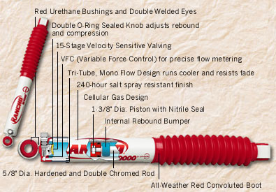
Since the installation instructions are oriented to the conversion of existing Ranch Shocks, it lays out the order of steps assuming the shocks are already installed. Instead of installing the shocks first, I installed the fittings onto the shocks on the bench - why contort myself if I don't have to! The conversion involves the removal of the rotating control knob and the installation of the air fitting and "O" ring. This was pretty easy to do on the new shocks that Dave bought. The control knobs come off easily and the air fitting and "O" ring just take their place. Once the air fittings were installed, I installed the shocks. I suppose there are folks who think it is easier to do with wheels removed. But we just drove the Jeep up on ramps and swapped out the shocks. There are no special considerations except to say that the fasteners from the old shocks are reused. The new shocks come with bar pins inserted for the rear shocks and a new nut for the top shaft on the front shock. They also are supplied with new bushings already installed on the rear, and ready to install on the top front. |
|
|
Time to install the shocks. We debated mounting the air connections at the top where they would be protected. In the end the decision was made for us in the front because the shocks will only mount one way. It was no big deal up there because the air connection is sufficiently protected from knocks by the way the shocks are mounted. In the rear, we oriented the air connections to point toward the front of the vehicle. This places them inside the lower shock mounting bracket, again, well protected from most types of damage. |
|
|
Air Line Manifold Location and Installation |
|
|
We had to decide where to locate the two manifolds that distribute the air connections from the compressor. We considered mounting them under the Jeep on the frame rails. We looked at various places in the engine compartment. In the end, we decided to mount it on the bracket that is adjacent to the ABS shelf, near the shock system compressor. I drilled a new hole and we bolted the two manifolds side-by-side. This places it away from engine heat (well high heat anyway), up where it is accessible for maintenance, and out of the elements. I think it turned out to be a good place for it since it made assembly quite easy. This location will not work for Jeeps with ABS or other components installed on the ABS shelf. |
|
|
Air Line Locations and Installation |
|
|
The air lines need to be routed from the distribution manifolds to the shocks. There is one line for each shock. The purpose of the line is to activate the valve formerly controlled by the rotating knob that is removed when the remote control is installed. The entire system has to be air-tight. The air lines are connected to the shocks and travel along the axle and frame to the manifold and compressor. This means that the air lines must transition from the frame (non-moving) to the axles (moves with movement in the suspension) |
|
|
I decided not to hurt my head figuring out how to solve the problem of mounting the air lines to the shocks in such a way that the lines would be protected and move without limitation. My source of inspiration was my own Jeep: It has ABS and each wheel has an ABS sensor. This wiring has exactly the same considerations and nearly the same mounting points throughout. It was a very easy matter of reviewing my ABS layout and then routing the air lines the same way on Dave's Jeep. |
|
|
Basically the air lines descend down from the air compressor to the frame rail below the driver's feet. From there, the front lines follow the left lower control arm. The left line connects to the left shock. The right line is wire-tied over the top of the axle to the other shock. I used some wire loom wrap to protect the air line in places where movement was possible. The rear lines follow the brake lines all the way back to the rear axle where the left and right lines branch off to their respective shocks. |
|
|
Each air connection requires a different length of air line. We "fished" the line back to the shock in question from the front of the Jeep, making sure not to tangle the air line in any other wires or lines. I wanted to make sure that any other systems were left separate from this one so that servicing will not be complicated by tangles. This required fairly constant watching to make sure that we kept ourselves honest. This was especially true working around the steering column since it would not do to have the air line get wrapped in the column. |
|
|
We fished each line down to a shock, left a little bit of slack and made sure that each change of direction had plenty of curve to prevent kinks. I cut each air line connection square, starting the job with a new razor knife blade. I put a connector onto the air line, added the itsy-bitsy "O" ring, then connected the air line to the fitting, making it finger tight. I made sure to seat the air line in the connection, and avoiding cross threading and over-tightening. Naturally I made sure that no dirt got into the system. |
|
|
We worked our way through this slowly, taking our time to check and recheck the routing of the lines. When we were satisfied that the lines were properly connected, we organized the air lines and wire-wrapped them to the main wiring harness on the fire wall, routing it away from the exhaust manifold and steering column. Two openings on each of the manifolds are to be closed off - they are for use in dual-shock applications. I put the plugs for these in and screwed on the connectors. |
|
|
We left the gauge lighting wires unconnected. Dave will connect them to something that receives power when the other dash lights receive power - probably another dash light power source can be borrowed to power these lights. |
|
|
Testing and Troubleshooting |
|
| Once all the lines were run, all the components were in place, and the shocks were converted and installed, we were ready for our first test. This came after a leisurely afternoon of slow working, talking, more working, and breaks for food and drink. We hoped it would work with our first try. We hoped there would be no air leaks or component failure. Dave started the Jeep and pushed the control for the compressor. The needles swung into action and climbed towards the "5" on the dial. When they reached it, he let off the button. Immediately, the gauge for the rear started going back down to zero. The gauge for the front slowly did the same. We had a leak somewhere... Darn! it was already dark and we were both tired. Neither one of us was interested in a long protracted diagnostic session. So we took a sanity break and let it sit for a minute. We took a drive to see if we could feel the difference in the shocks, playing with the controls to see if anything improved. It did not. | |
|
After we cleaned up the accumulation of rubbish that had collected while we worked, we decided to check the connections for leaks. We erroneously concluded that there must be a problem with the rear side since that was the side that had leaked down fastest. That reduced the number of fittings to check. I mixed up some clean soapy water and dribbled it on the manifold connections while Dave ran the compressor. Immediately the problem became obvious. The four plugged connections were spewing bubbles like a child's toy! I had not installed the "o" rings on these connections because I didn't think they were needed. DOH! I could not have been more wrong. I put the O-rings on and we repeated the test. This time, the pressure did not leak down. When Dave pushed the button for the compressor, the gauges went up to "5" and stayed there without moving. We took it for another ride on the road and this time we were treated to the full operation of the system. |
|
|
We set the shocks to various settings from "1" (Soft) to "5" (Hard). The system works like a champ. Dave can match the shocks front and rear or run either the front or rear softer or harder than the other. The separate adjustments are somewhat strange because pressurizing the system loads up all the shocks to their maximum pressure setting. So you have to bleed down the end that you want to run softer after pressurizing all four shocks. It's not really too bad, just takes some getting used to. |
|
Return to Jeep Specs Page
Shop for Jeep Toys and Books | See the Toy Jeeps | Off-Road Index
Photos, Layout and
Design © 2002 Paul M. Provencher All Rights
Reserved.
Contents of this Web Site may not be used without written permission
Visitors since 6/23/02