After installing driving
lights I was thinking about the implications of forgetting to shut them off.
Having left my regular headlights on all day at work, I knew that it was possible to
forget these too. The warning buzzer usually saves me with the headlights - they're
easy to forget in the daytime. But even with the gentle chime that the factory put
in, I still have forgotten them twice in about five years.
Now I know that lots of people really dislike the buzzer
reminders for seat belts, keys, headlights, and so on. So be it. I don't
really mind them because they serve their purpose for me: I like to wear my seat
belt; I don't want to lock my keys in the vehicle; and if I can avoid killing my battery
as a result of a mildy annoying beep, I'll take it.
I did install a switch to disable my dome light when my
hard doors are removed. This does defeat the headlight and key reminder because
they're triggered by opening the doors. But fortunately the times I run doorless are
few so it's not a big "risk".
Back to the new driving lights. I wanted a buzzer
to remind me that they were left on if I shut the vehicle off. So I did some
searching on the internet. I figured that there would be a half-dozen cheap
solutions that would be available. It seems like just yesterday I saw them hanging
in stores like Wal*Mart, K-Mart, and other department store auto sections where you can
buy gizmo's like this. But these days, most cars come with these features and I
guess nobody goes shopping for them anymore.
Nothing surfaced after a casual search on the internet
except a few wiring diagrams for making your own. I visited K-Mart, Wal*Mart and
Auto Zone. Nothing-Nothing-Nothing. So I absorbed the wiring diagram, made a
list of the components and went to Radio
Shack. Before deciding to build the device, I checked to see if they had a
ready-made solution. No!
So I bought quite a collection of resistors, transistors,
buzzers, perf-board, project enclosures, etc. (Parts list below) I spent the evening
putting the circuit together. I hooked it up and nothing happened. I should be
quick to say that the circuit looks valid, and I bought the right components to make it.
I believe I translated the circuit diagram to the circuit board correctly and
assembled the pieces properly.
What I will not claim is that the connections are all
good. You may have heard of "booger welds"? Well, I am the master of
"booger soldering". I really didn't do a very good job of soldering the
pieces together onto the board. And those that I did solder well got pretty hot so
there is no telling if the component survived the heat.
I felt bad that I had failed this excursion into circuit
assembly, but also realized that more practice would probably improve my skills and yield
a working item. I had even purchased duplicate parts with that in mind. But
the bottom line was I wanted to install a headlight warning system more than I wanted to
become proficient at soldering components onto a circuit board. There had to be
another way.
I got more aggressive with my searches on the internet
and found a ready-made
unit for $20 that would control not only my driving lights but two other devices as
well. That's nice but I really just needed something simple.
In the category of simple, the best solution I found was
one where you simply put the positive lead of a buzzer to the device you wish to monitor
and the negative lead to a ground point that is only grounded when the vehicle is turned
off. When your device is on and the car is off, you get a circuit and your warning
system comes on! On Honda Civics the car-off-ground is apparently part of the
defrost circuit. I liked the brute simplicity of the solution but was not in the
mood for reading the schematic for my Jeep in the vain hope that I could figure out which
ground in my Jeep was only grounded when the vehicle was turned off. I needed
to figure this out and get something built.
Then I thought of the relay that controls the driving
lights. The basic principle is that the relay makes a connection when power is
applied. When power is turned off, the connection goes away. On Bosch
relays that have both "87" and "87a" terminals, there are two
connection points - one that is active when there is no power (87a) and one that is active
when power is applied (87).
I did some thinking and realized that I could use a relay
to control my warning system. I would set it up so that when the car was off, the
relay would provide a path to ground and when the car was running, the relay would
disconnect the ground. This would provide the switching for "car on"
versus "car off". I would take my power for the relay from the Auxillary
Power lead in the dash that was switched on and off when the car is turned on and off.
This will control the relay. Now I have a way to turn off the ground when the
car comes on. This has the effect of cancelling the warning system - it's OK to have
the lights on when the car is running.
The other piece of the puzzle is the driving lights.
I need to have a way to let my system "know" that they're On. This
is easy. I simply connect the positive (power supply) lead for my system to the
positive lead coming from the switch that turns on the driving lights. If the switch
to the lights is on, I have power to my system. This is the power that goes to the
buzzer and warning light. If the driving lights are on, there will be power to the
warning system. If the car is off at this time, there will also be a ground and the
system will be activated. Clear as mud?
See the How Stuff Works web site for a decent explanation of the relay
operation, it's not really that complicated. The important thing to remember is that
you need a relay that gives you a way to complete a circuit when the car is turned off and
there is no power to the relay.
So I went to the Auto Zone near work and took a look at
the generic relay that they sell for their generic driving lights. It looked OK and
I was getting ready to purchase it when I took a close look and discovered that there were
two "87" terminals and no "87a" terminal. Basically, there was
no connection made when the relay was not powered so I would not be able to use it in my
design.
I decided to go back to Radio Shack to see what they had.
At first it looked pretty dismal - most of the relays they have are either 120VAC
or they do not have the proper terminals and operation. But I found a perfect relay
for the job.
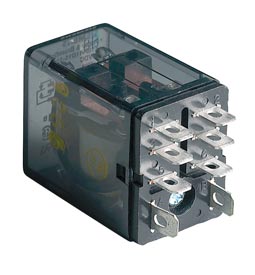
275-218 DPDT Plug-In Relay
What's good about this relay is that it is 12 VDC,
handles 10 amps, and has terminals for both the On and Off relay positions. A side
benefit was that this relay could control more than one device. I bought the relay
and a buzzer. I already had a light from my last trip to Radio Shack.
I had to translate the Bosch circuit layout for the Radio
Shack relay. Here are both the Bosch Relay and the Radio Shack Relay circuit
layouts.
Bosch Layout
(Above)
Radio Shack Layout (Above)
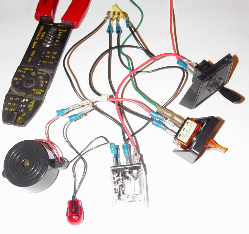
I built the circuit on the bench and tested
each component and the incremental pieces as I went along. First the buzzer - yup,
it works. Next the warning lamp, yup, good to go. Then the relay. OK.
Then I added in the switch to simulate the driving light switch - no problem.
Then a switch to simulate the key - Still cooking with gas...
All this running off a 12VDC converter that I have for my
GPS, running in the house on 120 VAC. There is no sense freezing my butt off and
contorting myself. Not to mention swearing about the working conditions and mistakes
I would undoubtedly make. The other reason for building it on the bench is to be
sure it doesn't catch on fire... The last thing I need is to test it out and have
the rig go up in flames. Not that my year already hasn't had stuff pretty close to
that anyway...
Here's a picture that really sucks but shows the general
area where the Auxillary Switched power source is on my Jeep. Later Jeeps may not
have it. You will have to find a 12VDC power source that is always and only on when
the Jeep is on. (No, not the fuse with the red circle and the arrow, silly, the
wires with the white tags on them - the white arrow is pointing to it). The black
wire is the one, labeled "SWITCHED AUXILLARY POWER 3 AMP MAX".
With everything working the way it should, I removed the
switches that I used to simulate the installed configuration and, after consolidating the
ground wires to a single terminating connector, lengthening the leads for the warning
light, and installing the fuses (not shown in photo), I removed the panel under the
steering wheel and the bezel in the center of the dash.
I already had a hole on the panel under the steering
wheel where I had originally located the hand throttle. When I installed it I had
found that the housing interfered with the dash. I had to redrill the panel to
accomodate the throttle cable. That left a hole that has been there for a couple
years... I drilled this old hole to the proper size for the warning light and
installed the warning light into the hole. That took care of the "spare"
hole and got the warning light installed in the dash. I connected the warning light
leads to the relay and connected the shared ground from the warning system to the ground I
used for the driving lights.
I routed the two power leads to their respective
locations. First the power feed to the buzzer and warning lights were routed to the
driving lights "load" lead that runs to the driving lights relay. This
way, when the driving lights are on, the positive size of the warning circuit is charged.
Then I routed the power lead for the relay to the
SWITCHED AUXILLARY POWER factory lead behind the glove box. I am already using this
lead for a few items and simply added another doubling connector to accomodate this wire.
When the Jeep is turned on, this powers the relay that disconnects the ground
circuit for the warning light and buzzer. As long as the key is turned on, power
runs to the relay and prevents the completion of a circuit for the warning light and
buzzer.
I put some electricians tape on all the connections to
prevent them from coming apart, getting wet, or shorting out against anything. Then
I reinstalled the panel under the steering wheel and the dash bezel.
Now, when the key is turned off while the driving lights
are on, the positive lead is "hot" and connects to the warning light and buzzer.
The ground, disconnected when the key is on, now is connected and the circuit is
complete: The warning light and buzzer come on.
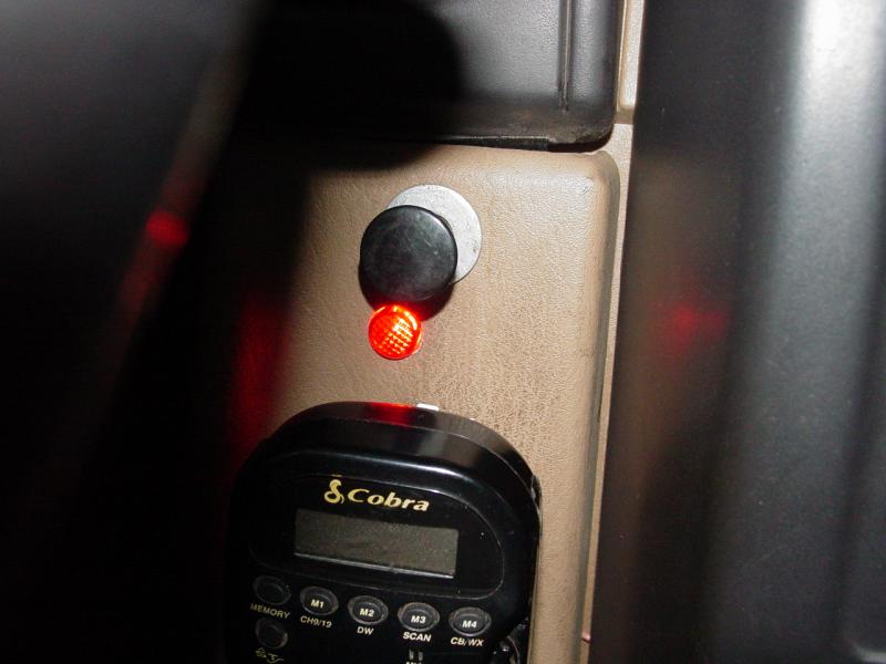


I placed the relay and buzzer behind the panel below the
steering wheel where it can still be heard from outside the Jeep! Then I tested it.
I turned on the key and the driving lights. Nothing. No buzz, no
warning light. What could be wrong? DOH! My brain wiring - the buzzer
and warning light do not do anything unless the key is off. So I turned the key off
and the warning light and buzzer came on. I turned off the driving lights and the
buzzer and warning light went off. Test complete with success!
So of course after all this, I thumbed my latest J.C.
Whitney Catalog (how did they know I moved...) and there it was: $7.95 for a
Headlight Warning Buzzer... Now the thing that really frosts me is
that I searched their web site before I started all this and it wasn't there...
Truth be told, the exercise of building this was interesting enough to make it worth the
trouble. And I think it produced a better solution than the one I could have bought.
Parts
|
275-218 12VDC/10A
DPDT Plug-in Relay
|
|
|
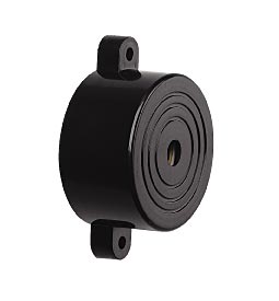
273-080 Piezo
Pulse Buzzer
|
 |
|
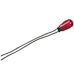
272-332 12-Volt,
Red Snap-In Lamp
|
 |
|
Fuse Holder - I got a fuse holder that
would handle 20 amps even though the circuit only calls for 10 amps.
|
 |
|
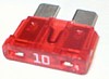
10a fuse - To place in the fuse holder.
|
 |
|
Parallel Splice Crimp Connectors (fuse
holder to extension wire)
|
 |
|
18-gauge wire
|
|
|
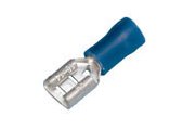
Female Disconnects (wires to various
connectors
|
 |
|
Electrical Tape (wrap bare connectors on
dummy fuse)
|
|
|
Wire Cutter/Crimper Tool and Screw driver
(Philips)
|
|
|