The Almighty Power...
As with my
Crossfire, I wanted to put in switched
and un-switched fuse panels to support the need for the
hands-free phone,
drive +
play iPod controller, XM radio and
GPS, and a couple open accessory
plugs. I priced
Painless Wiring fuse panels and opted to replicate them with
parts sourced locally. Here's a list of the parts used in
the event you wish to order them online and save gas and a trip
to the store.
|
Product |
Mfg |
Part# |
|
|
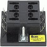
ATC Blade Type Fuse Panel |
Buss |
BP/15600-06-02 |
|
|
Automotive Wire 12 gauge red |
ElectroForce |
89325 |
|
|
Automotive Wire 12 gauge black |
ElectroForce |
89324 |
|
|
Automotive Wire 10 gauge red |
Painless Wiring |
|
|
|
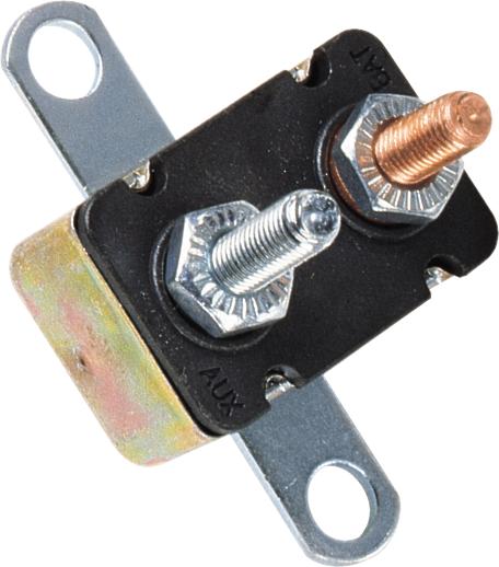
30 Amp Circuit Breaker with Mounting Bracket |
Buss |
BP/CBC-30HB |
|
|
Fuse Assortment ATC Blade |
Buss |
AK-6 |
|
|
Repair Tape |
SealWrap |
http://www.sealwrap.com/tapedata.html |
|
4 Pin 30 Amp 12 Volt Relay |
Conduct Tite |
84601 |
|
|
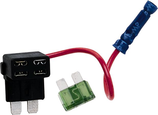
Fuse Tap |
Buss |
BP/HHA ATC Fuse Tap
|
|
|
|
|
|
|
This provides
auxiliary power options for these and future devices.
The wiring plan
takes power directly from the battery, through a 40 amp circuit
breaker.
This reduces the risk of fire from the hot
lead from the battery passing through the firewall. Even with
fuses for the components inside the cabin, the run of wire from
the battery to the firewall could fault and cause a fire without
a breaker of some sort.
The un-switched
fuse block provides power at all times no matter the car is on
or off. I like to use this for the GPS, XM Radio, and is
required for one terminal in the
Drive+Play. After a
few generations of changes, this is a typical arrangement of
connections to the auxiliary fuse panel.
The switched
fuse block is controlled by a 30 amp relay that is activated by
a switched lead (terminal 86; terminal 85 is grounded to
chassis) from the original fuse box.
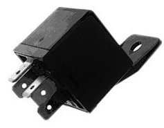
When the car
is on, the activating lead (86) switches the relay to provide power
to the fuse box (power supply connected to terminal 30; terminal
87 provides power out when relay is "on"). This relay does
not provide terminal 87a which would give power out when switch
is "off". When the car is turned off, the switch
lead power
drops, allowing the relay to disable power from the battery.


The leads come
through the firewall using a factory-installed plug that has
provisions for wiring to pass through.
Here, I
added the fuse tap to the existing auxiliary fuse panel. I
removed the 15 amp fuse from socket 10 (the switched power lead
to the stereo), put the fuse onto the fuse tap and added a
second fuse for the new lead it adds (not shown in picture for
clarity), then put the cover back on the fuse panel. That
was easy!
Next I put a
spade connector on the positive battery terminal and installed
the 40 amp circuit breaker between the battery and the hot lead
that goes through the firewall into the passenger compartment.
This info may
be useful in wiring the "always hot" connection or "switched"
connection - need to check car first.
This lead
provides power to both new fuse panels - one directly and the
other through the relay that is switched by the lead attached to
the fuse panel as just described. This approach
provides safe power to a number of accessories without
modification to any of the car's fuse boxes or harnesses.
Each accessory
is added by putting spade connectors on the end of the hot
wire(s), and an eyelet connector on the ground wire. The
hot wires are connected to available fuse rows in the panel
("always on" or "switched"). The
ground wire is connected to a suitable chassis ground.
I placed the
auxiliary fuse box behind the panel under the steering wheel (it
snaps open)...
I undertook a
marathon install of all my usual electronic components starting
with the fuse panel. It went smoothly from start to finish
and by the end of the day I had everything up and running!
MINI Cooper Electronics Marathon Install
| MINI Cooper
Auxiliary Audio Input |
harman/kardon drive + play |
Garmin V GPS |
Motorola HF 850 Bluetooth Hands-Free |
Delphi Roady XT XM Satellite
Radio | Factory Radio
Here's the
final configuration: