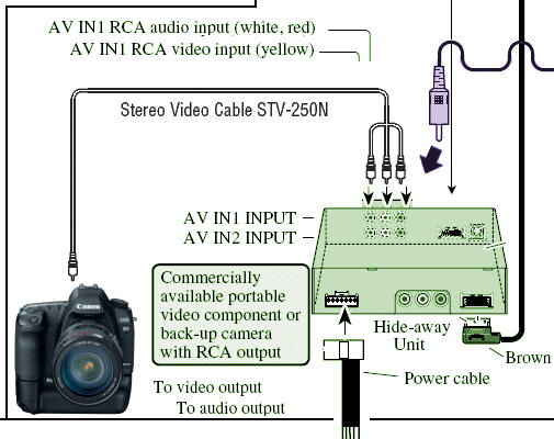
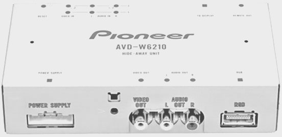
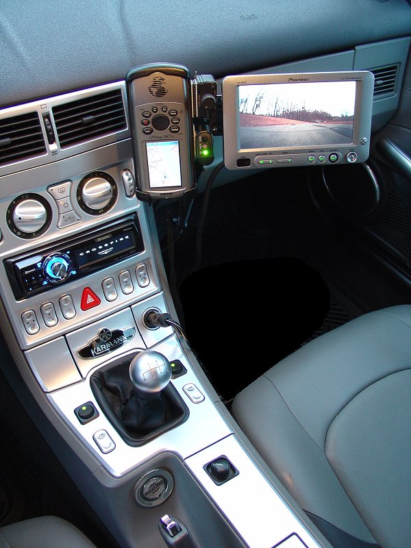
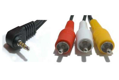
and plugged the whole thing in
- as easy as plugging three RCA plugs into the AV
IN1 labeled "video out" ports.
The
screen has a button that switches between "AV" and "NAV".
With the proper screen defaults, that's all that is
needed to switch from back-up camera/Vehicle
Dynamics Processor to camera!
There's
really not much to this installation.
I already have the video controller with
open terminals. I already have the
power connections and open AV inputs.
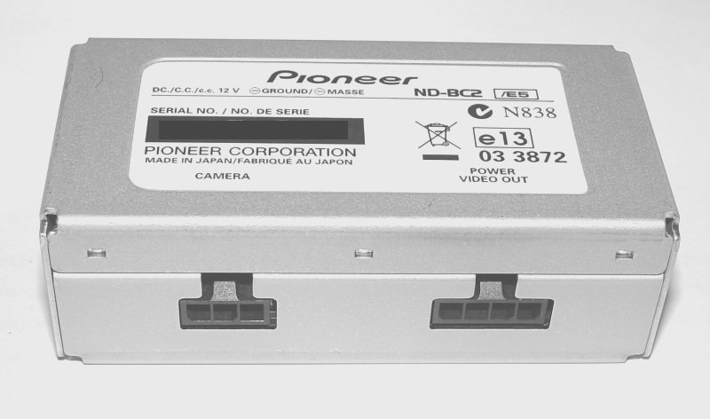
I can use the plug on demand, leaving it stowed when
not in use, and the cable snakes through a
hole in the rear fascia. The video
screen was already mounted and cabled.
All the hard work was done when I put in
the VDP-1.
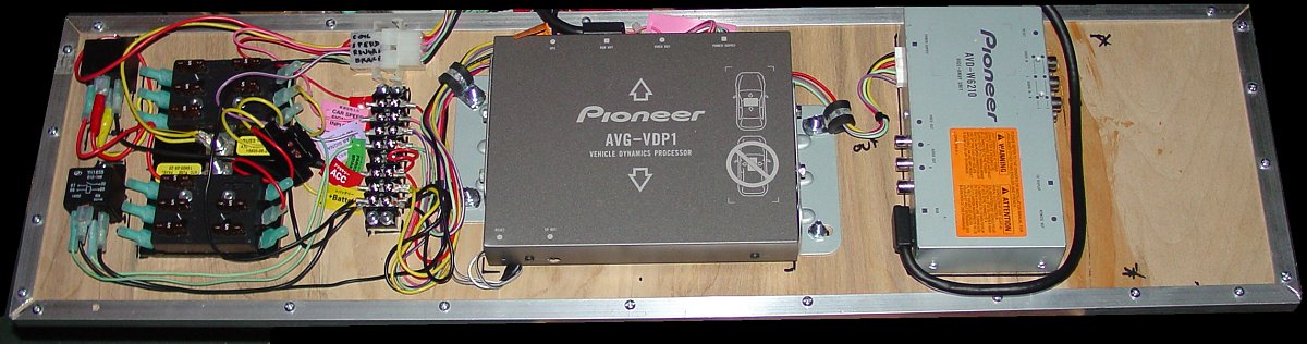
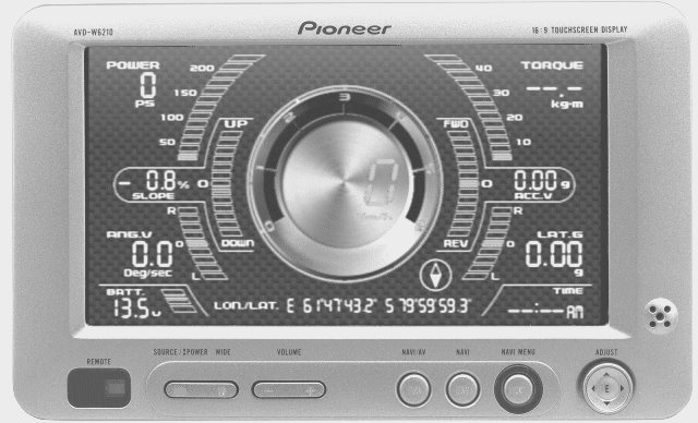
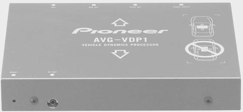
This
augments the drawing that shows the
AVG-VDP1 and AVD-W6210 components
already installed. Click to see
the detailed drawing including car
electronic systems.
The
control panel itself was simply velcro'd
to the space for this purpose left on
the component board.
View On Demand
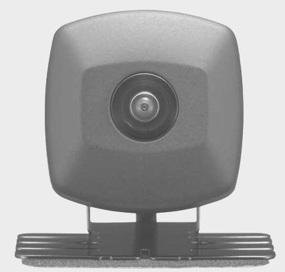
I
wanted to have the camera
monitor available on demand without putting on the emergency
brake.
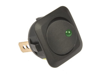
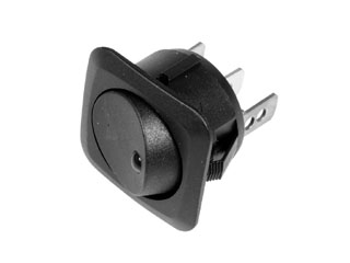

(switches below
are similar but with round instead of square edges)
Carefully
measuring to make sure the structure of the
panel would not be damaged, and to assure
the space behind the panel was deep enough
to allow switches, I marked the switch
locations - carefully lined up with the
window switches, and parallel to each other.
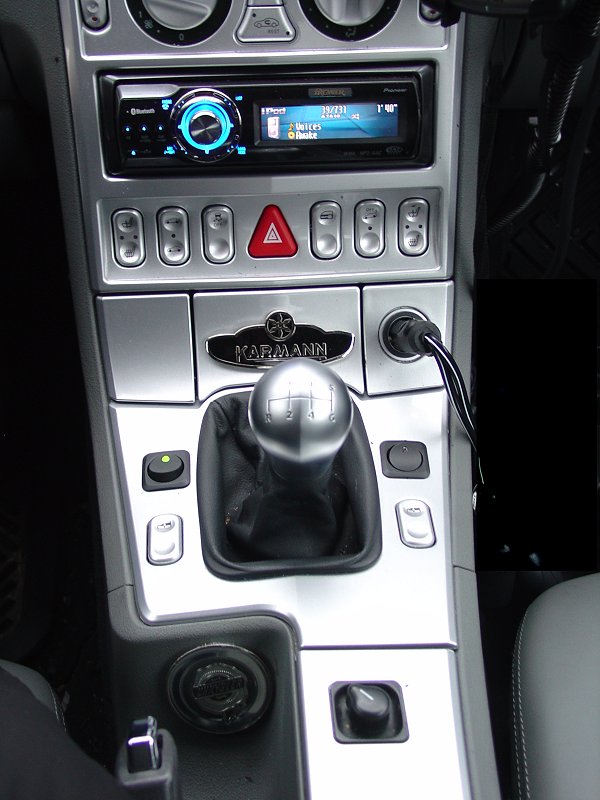
When the switch is
activated camera monitoring is enabled. The rest of this
install was performed previously in support of other components
and was simply reused.
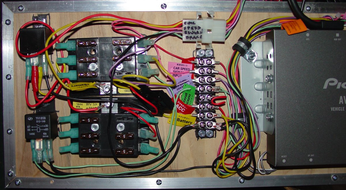
Fuse Panels
Since this
subsystem has so many elements, I decided to
incorporate another pair of fuse boxes.
One fuse box takes a 12-volt (+) feed from
the battery with a 30-amp circuit breaker providing
protection between the battery and the
firewall. This lead supplies the power
to the "un-switched" fuse panel.
This power is
fed through another relay that is activated
by the same factory-original fuse panel feed
that is activated by the key (and controls
the stereo). When the key is turned
on, the 12-volt signal activates the relay,
which makes the connection from the
un-switched fuse panel and provides power to
the "switched" fuse panel.
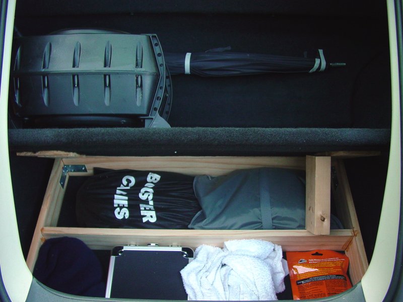
Component Construction
I
previously constructed a storage compartment
by creating a four-inch deep insert that
goes into the cargo area. I fabricated
a heavy-duty cover and carpeted it to match
the car. To this I attached my
sub-woofer. The compartment is not
easily detectible. Here it is shown
open.
For this set
of components, I took a 1/4" piece of finish
quality birch plywood. I laid out the
parts as described in the wiring plan above.
Then I attached the components to the panel.
I left some room on the right for the
rear-view camera control box (I can dream,
can't I?) and space between the components
for airflow and wiring.
Using a
variety of small hardware fasteners, I
anchored all the pieces to the panel.
Then I added a border on the panel to give
it rigidity, and to raise it up slightly off
the floor of the compartment.
In order to be
sure it would be easy to remove the
components, I created a harness for the
leads that go to various parts of the car,
isolating the board and components so that
only the harness connector need be separated
to remove the entire unit. This is
necessary because the tire repair and
jacking equipment lie under the compartment.


The finished
product is workmanlike, not something to
open up and show off at a car show.
That's not what I made it for. I just
wanted the parts to be anchored down, easy
to move as a unit, and with as few wires as
possible. I could have spent a lot
more money and time to make it pretty -
maybe someday...