Installation
The
installation of this group of components
is extremely challenging.
There are many connections to the car
wiring harness. Additionally,
there are several components that make
up this functional unit so there are a
number of connections just to configure
the basic boxes and display. And there
are some things that are not documented
in the owners and installation guides...
I did not get much satisfaction calling
and writing to Pioneer. The web
site support responds by saying I need
to call. Then the person I talk to
when I call reads the manual to me...
Bench Testing
Make no
mistake - without the very detailed
wiring and installation plans, a clean, organized
installation of this many components, with
this many wires and connections, success
would be at risk, and troubleshooting nearly
impossible. So if you have just
glossed over the wire diagrams, comments
about RPM calibration, coils, power and so
on, and think you can just grab your boxes
and run out to the car - stop!
I had the
benefit of assembling the circuit diagram
from all the sources (factory service
manual, navigation radio installation
manual, Pioneer component installation
guides, and the MSD interface guide, I feel
ready. That right there is almost 20
hours of "studying".
I am still not
ready to get into the car. First I
decided to assemble the units on the bench.
This required the purchase of a 120 volt to
12 volt converter. Don't go buy a
dinky one at WalMart. Those are made
for powering little devices with 100-300ma
power requirements (that's no more than a
third of an amp). The Pioneer devices take
as much as two amps each. Just for fun
I tried to power them using a 300ma converter. Nothing
worked. Not enough power.
I purchased
a unit meant to power small 12v cooler that
puts out six amps continuously. Watch
out for some units for sale that only put
out a rated amperage for a short time.
You may want more test time than the unit
can be run! Here's the one I got.
A good compromise between price and power
output, with 100% duty cycle (that means it
can run continuously).
With this
device, I had a suitable test set up and I
was ready to start putting things together.
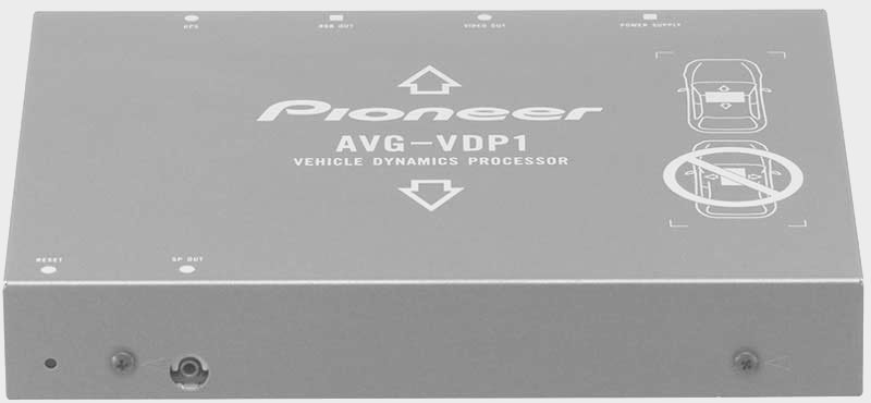
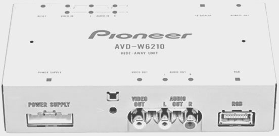
First I
assembled the control units to their
respective devices - the AVG-VDP1 to the
AVD-W63210 Hide-Away unit.
Next I put
connectors on all the wires. With
these basic steps done it was time to test
for basic operation of the display and
processor.
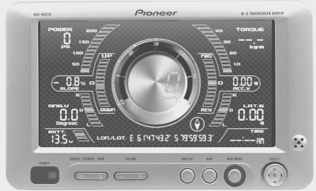
I was happy to
find that the display powered up and the
AVG-VDP1 ran through it's start-up screens.
The menus all worked and the GPS soon
acquired several satellites (with the
satellite antenna placed outside with open
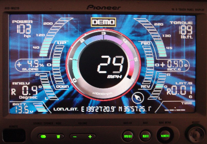
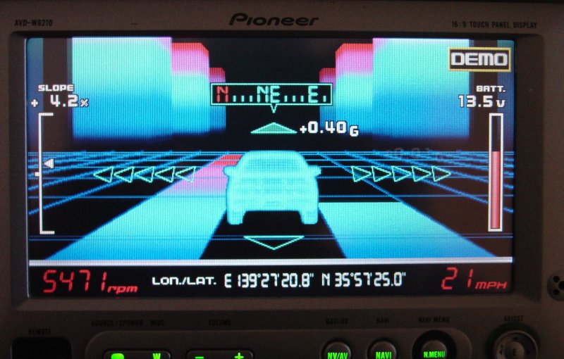
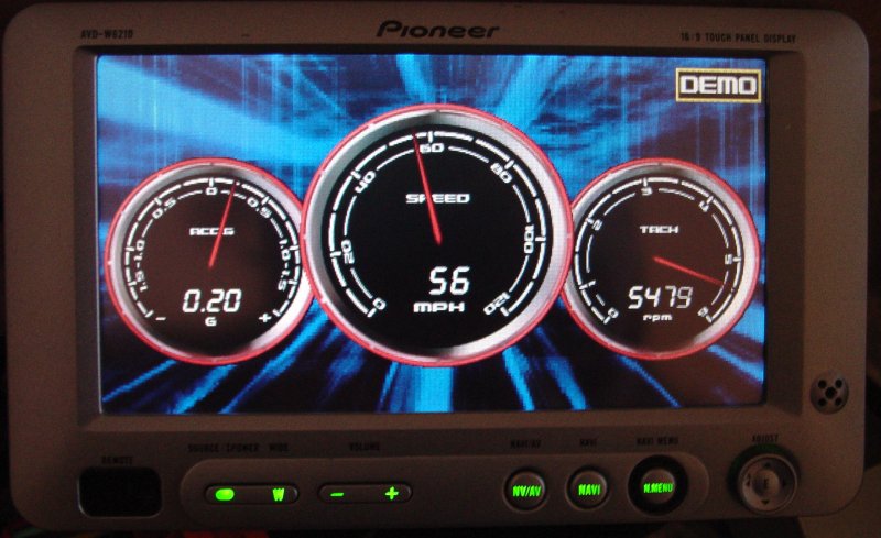
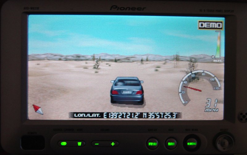
sky above it. Since the live screens
were pretty dull because the unit was not
moving, here are some of the demo screens
that to photographed on the bench.
With these
basics out of the way I knew that the boxes
and display work and I moved my attention
to the car. It needs to have wiring
harnesses fitted, connection points selected, clean harness extensions, and connectors
put in place. That kept me busy for a
a few hours...
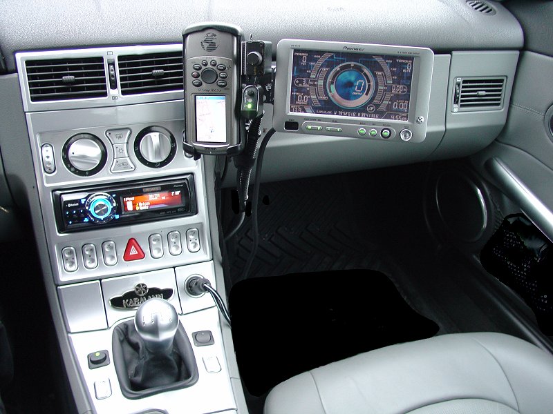
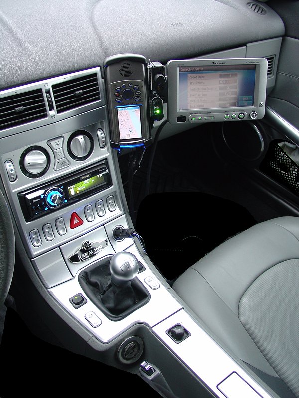
Monitor Installation
I chose to install
the touch-screen monitor on my existing Panavise bracket that
holds my GPS, radar detector and BassLink Remotes. I was
necessary to add an extension bracket, reinforce it with a short
piece of aluminum angle-stock, modify the swivel head so the
monitor would remain close to the bracket, and to manage some
wires. With this out of the way (no small task as the
bracket parts had to be custom made and hardware to fit
purchased and tested. While the end result is by no means
pretty, it does allow the glove compartment to be opened easily,
and does not wobble around or obscure the view through the front
window.
Speed and Reverse Signals
I relied
heavily on the factory service
manual for the Crossfire (to understand
the various control modules in the car,
the location and ratings of various
signal sources; the installation guide
for the Crossfire factory navigation
radio (provides the best connection
locations for the Speed signal and
Reverse Switch controls).
The drawing that
follows comes from the Crossfire Factory Installation Guide for
the Factory Navigation Radio. It shows the location of the
Speed Signal and (if you like it) the reverse signal. This
is how Chrysler recommends making these connections.
Here's an
alternative to the reverse signal that I opted to use. I
didn't want to cut into the harness shown in the drawing.
It was just too neat and tidy to start hacking into. But
what really convinced me to go another route was the fact that
the lead would have to run the length of the car to the
components in the rear. Why not just use the reverse lamp
lead in the back of the car and have a short run to the
component?
It's the 12-volt
lead to the lamp (Gray/Yellow) wire that connects pin 5 on
either the right or left rear lamp assembly, concealed behind a
removable panel. I found it easy to snake the wire up
behind the interior trim panel from below and attach using the
same approach shown in the splicing illustrations above. I
added a connector to the new piece of wire so that I could later
remove the lead without unsoldering the lead.
RPM
Signal
The most
challenging part of this installation is
the identification of a suitable power
source for the ignition-controlled 12v
lead. The issue is that this unit
uses vehicle engine RPM as a key
component of data in its calculation of
the various outputs. Without an
accurate RPM reading, the unit is
useless.
It may not
seem a very tough thing. Indeed,
at first I read the manual and saw only
12v leads for continuous (battery) power
and switched power. But then
thinking about my Pioneer DEH-P980BT and
the Vehicle Dynamics it offers, I
recalled that the RPM calibration
doesn't work. I got to thinking
about this and got on the web. And
it didn't take long before I discovered
a dirty little secret about this device
- many people have been unable to
calibrate RPM's and so the unit is
practically useless to them. I was
determined to figure out what almost everyone else had missed
(including the support line at Pioneer...).
The
problem for all of them is simple -
newer cars use breakerless, electronic
ignition. These vehicles have a
coil bank or coils for each spark plug.
Additionally, these cars (and the
Crossfire has gone to great length here)
have very elaborate noise-suppression
circuits to prevent ignition noise from
being transmitted through audio systems
and other entertainment systems that
have speakers. The "noise" that it
is suppressing is the waveform that the
Pioneer AVG-VDP1 uses to detect engine
revolutions! So in short, modern
electronic ignition such as that found
in the Chrysler Crossfire prevents the
device from working if it is wired like
a stereo.
I went
through a lot of trouble to isolate my
power for my stereo so that it would not
transmit noise. So connecting this
device to my stereo power sources was a
non-starter. But what was I to do?
There had to be somebody who figured out
how to get around it for their car.
After
several hours of drilling into searches
I finally found a single post from a
person in Australia who described a way
to wire the unit to overcome the
problem. Essentially, the power
sources are taken from one of the
sparkplug coils and isolated from the
battery using small diodes. This
approach would work for some vehicles but not the Crossfire.
I reproduced it here for those who are looking for a solution.
I drew
it out below. In actual practice,
though I did install this wiring
initially, I removed it because in the
end, I found another solution that was
less complex and very reliable. I
have left this drawing but be advised it
is not applicable to the Chrysler
Crossfire. Read on.
This lead
me to stop and consider what I was
getting myself into. And I decided
it would be best if I cracked open the
factory service manual for the car and
identify all the connection points ahead
of time so that during installation, I
would not have to go back and forth from
the manual to the car a million times.
I ended up drawing a very detailed
wiring diagram (included) and in
the process reached the conclusion that
I was going to have to solve the RPM
calibration issue or give up on the unit
altogether. So I got busy doing my
research and after about 3 hours found a product that answered the
mail. I should add that in the
course of two phone calls and one email
to Pioneer Support they had no clue
and
could not tell me anything about this
detail. That's what they get for
outsourcing their support center...
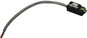
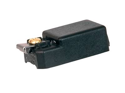
What I found is a Tach Signal GMR
Pickup from MSD.
It works
by detecting the signal going to the
coil pack on the spark plug, then converting a 12v input
to something the RPM detector in the
AVG-VDP1 can
calibrate to. For my application
that means attaching the tach signal
pickup to one of the coil pack positive
leads.
The MSD GMR pickup
can be used with inductive or capacitive
ignition types to provide an rpm signal
of 30% duration when the ignition coil
fires. Two washers are provided with the
pickup and must be installed in one of
two positions depending on the type of
ignition driving the coil.
Here is
the wiring diagram from MSD:
Click the image above for the
Installation Manual

MSD Installation
Here's the
information from the factory service
manual regarding the coil pack on the
engine. The MSD device simply
clips onto one of the positive coil pack
input leads. One lead goes to
ground, another to the switched 12v
positive power source, and the last goes
to the wiring of the AVG-VDP1 as the
Switched Accessory Lead.
The
instructions below are provided to give
a sense of where the coil packs are
located and how to reach them, do not
continue past step 2 since it is
unnecessary to remove them. Just
familiarize yourself with the
location and then install the
MSD unit according to the
instructions provided with the
unit. It took me more time
to remove and replace the air
filter cover than to attach the
clip to my cylinder number six
coil 12-volt input lead...
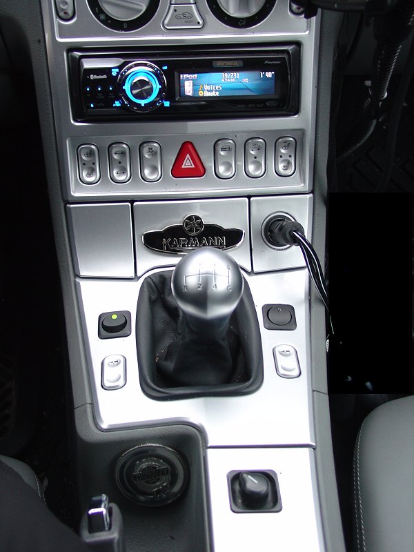
Switch Gear
After careful
consideration, I decided to install the
switches on the panel that surrounds the
stick shift. I managed to find two
switches that have a similar form factor to
the side-view mirror knob.
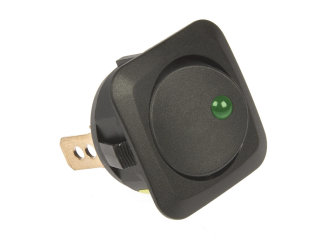
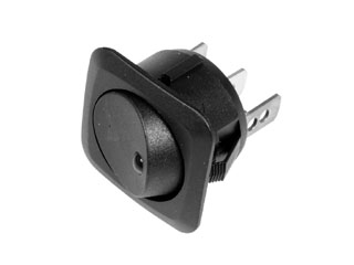

(switches below
are similar but with round instead of square edges)
Carefully
measuring to make sure the structure of the
panel would not be damaged, and to assure
the space behind the panel was deep enough
to allow switches, I marked the switch
locations - carefully lined up with the
window switches, and parallel to each other.
With no going
back, I drilled the holes needed (with a
center punch mark, small pilot hole then a honking 15/16"
speed-bore) to install
the switches. This was the only point
in the entire installation where I felt there was no going back.
One slip of the drill and this highly visible piece of interior
would be toast. There is no hiding a misplaced one inch
hole...
I was able to make the
holes exactly where I wanted them, and the
switches fit as planned. While they
are not silver and do not match the window
switches, I feel they are consistent with
the side view mirror control on the same
console so do not appear too out of place.
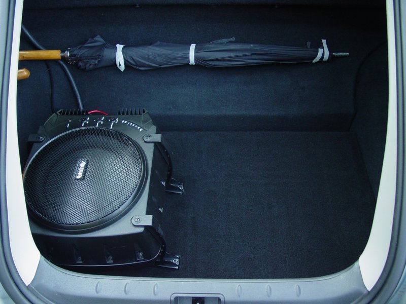
Component Construction
I
previously constructed a storage compartment
by creating a four-inch deep insert that
goes into the cargo area. I fabricated
a heavy-duty cover and carpeted it to match
the car. To this I attached my
sub-woofer. The compartment is not
easily detectible. Here it is with the
compartment closed. Not much to see, huh?
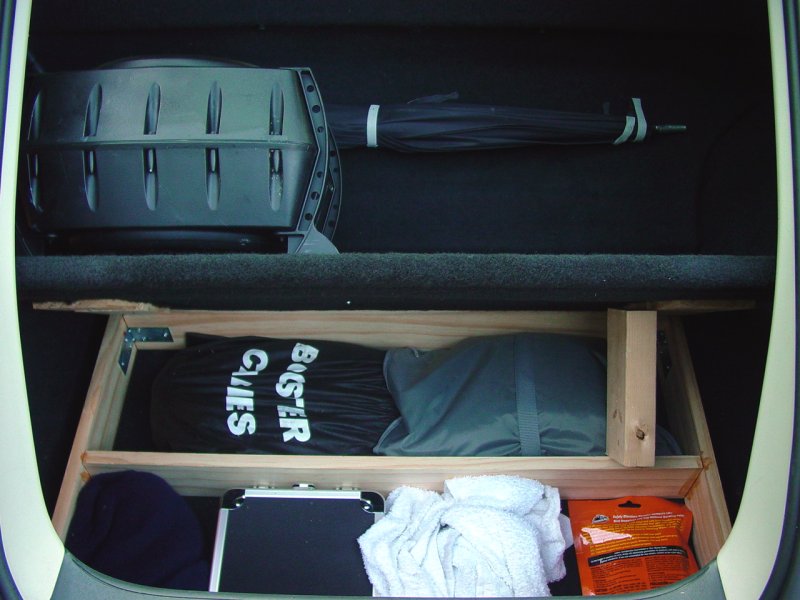
Here it is shown
open. Some of the contents were
removed to leave an empty compartment to hold the component
board and harness.
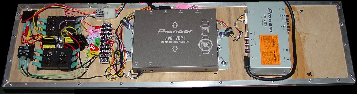
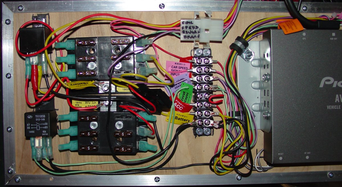
For this set
of components, I took a 1/4" piece of finish
quality birch plywood. I laid out the
parts as described in the wiring plan above.
Then I attached the components to the panel.
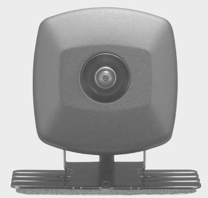
I left some room on the right for the
rear-view camera control box (I can dream,
can't I?) and space between the components
for airflow and wiring.
Using a
variety of small hardware fasteners, I
anchored all the pieces to the panel.
Then I added a border on the panel to give
it rigidity, and to raise it up slightly off
the floor of the compartment.
In order to be
sure it would be easy to remove the
components, I created a harness for the
leads that go to various parts of the car,
isolating the board and components so that
only the harness connector need be separated
to remove the entire unit. This is
necessary because the tire repair and
jacking equipment lie under the compartment.
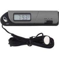
Cooling and Monitoring
Realizing the
compartment with the components will get
warm, I installed a small indoor/outdoor
thermometer that gives me the temperature
inside the cabinet, and in the car.
This allows me to monitor the temperature.
Since the wire was not long enough to reach
the dash and be concealed, I placed the
thermometer inside the console compartment
where I can refer to it as needed. The
side bonus is that the console compartment
contains the iPod so I can see if things are
getting too hot there as well. It's
all good...
After monitoring temperatures in
the compartment I found that the units do not produce much heat.
The temperature inside the compartment is only a couple degrees
higher than the temperature outside the compartment.
Still, in the dead of summer when the sun hits the black carpet
through the big hatch window, I am sure there will be plenty of
heat and some air flow will be necessary to preserve the life
and reliability of these electronics.
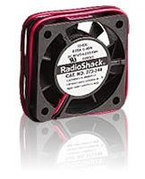
To keep the
components cool, I added a few vents on the
enclosure and installed a cabinet fan.
|
 |
|
Dimensions |
| |
|
Product Length
|
|
1.57
|
 |
|
Product Height
|
|
0.39
|
|
Product Width
|
|
1.57
|
|
General Features |
| |
|
Model
|
|
273-240
|
|
|
Product Type
|
|
Standard case fans
|
|
|
Recommended Use
|
|
Computer Builder
|
|
|
Body Material
|
|
Multi
|
|
|
Fits What |
| |
|
Model
|
|
273-240
|
|

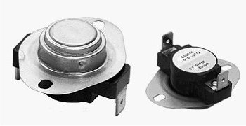
To control the fan I added a thermal switch
that comes on at 115 degrees and shuts off
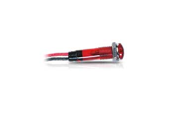
at 90 degrees. I added a warning light to inform
me that the compartment is above 115 and that the fan is
(supposed to be) on. This gives a fan
that self regulates and a monitoring indicator to let me know
when it's coming on. A quick test of the completed circuit
using the bottom of a cup of hot coffee to activate the switch
confirmed that it comes on and shuts off in the desired
temperature range.
It will probably run most of the time
on short trips on hot summer days (my inside thermometer
routinely pushes past 100°) but potentially could get the
component compartment cooled
on longer trips because the air conditioning will eventually get
the passenger compartment cooled and the fan will pass that
cooler air through the compartment. So far on cold winter
days, even for long rides, the component compartment does not
get any warmer than the main cabin. This suggests that the
components do not generate much heat, and indeed, none of the
installation materials make any special comment about airflow or
the need to cool the devices. Still it never hurts to keep
electronic component temperatures under control.
|
Red LED with Holder
Model: 276-270 | Catalog #: 276-270 |
- Mfg hole
diameter is 9/32
- Typical
Voltage: 12, with a maximum voltage of 16V
- Typical MCD:
33
- Typical
wavelength: 635nm
- Viewing angle:
25XXX°
- 15mA (max)
|
 |
The fan, LED, and thermal switch were
not installed at the time I took the pictures.
Component Panel
The finished
product is workmanlike, not something to
open up and show off at a car show.
That's not what I made it for. I just
wanted the parts to be anchored down, easy
to move as a unit, and with as few wires as
possible. I could have spent a lot
more money and time to make it pretty -
maybe someday...

Install Comments
Once you break
down the job into identifying the components, planning out and
executing the wiring sub-assemblies, installation is really not
much more than placing the finished component board into the
space you set aside for it (in my case a hidden compartment in
the rear hatch area) and then running wires to the connection
points, connecting the wires, then concealing them. I
added a couple switches to the mix, which required drilling out
the console. And I added the MSD sending unit for the RPM
signal, which acts as the 12-volt switched lead. But
really installing this in the car after all that, was just about running the
wires and plugging in the connector I made.
Here's an
evaluation of the installed
unit...
Overview |
Components |
Wiring | Installation |
Evaluation