Wiring
As I
worked through the exercise I found a
number of options for getting the
various signals. By looking at the
schematics I determined the best
approach overall was going to be to go
to the signal lead as it emerges from
it's respective controller. With
that basic plan, I drew the following
schematics.
They show all the
control modules involved, though most
control modules have only the relevant
connections shown. The drawing
would have been unmanageable otherwise.
And in any case, the factory manual
routinely shows sections of wiring
diagrams that focus on subsystems.
So I followed the factory manual
convention in that regard.
The
installation of this group of components
is extremely challenging.
There are many connections to the car
wiring harness. Additionally,
there are several components that make
up this functional unit so there are a
number of connections just to configure
the basic boxes and display. And there
are some things that are not documented
in the owners and installation guides...
I did not get much satisfaction calling
and writing to Pioneer. The web
site support responds by saying I need
to call. Then the person I talk to
when I call reads the manual to me...
I relied
heavily on the factory service
manual for the Crossfire (to understand
the various control modules in the car,
the location and ratings of various
signal sources; the installation guide
for the Crossfire factory navigation
radio (provides the best connection
locations for the Speed signal and
Reverse Switch controls).
I produced
a very detailed wiring diagram that took
into account all considerations of the
interactions between the components, the
car and the user. I decided to add
some features that would improve the
operability of the components, and to
add a key element that is not included
with the system, not documented, but
critical to its operation.
The image
below opens up to a very large wiring
chart that shows the major car systems
that tie into the Vehicle Dynamics
Processor. This drawing took a
fair amount of time to compile from the
installation guides and the factory
service manual for the Crossfire.
Click to open.
Notwithstanding my hard work to condense
and clearly organize the drawing, it is
very large, for internet purposes.
I have placed a scaled version of the
drawing in an Adobe Acrobat file for
easier viewing.
Click to View Full-size in Adobe Acrobat
I had the
benefit of assembling the circuit diagram
from all the sources (factory service
manual, navigation radio installation
manual, Pioneer component installation
guides, and the MSD interface guide, I feel
ready. That right there is almost 20
hours of "studying".)
The wiring
diagram above shows the various devices
and car systems. The surrounding
systems are shown for context. But they are not important when it comes time to
wire in the units related to the AVG-VDP1. The following
diagram is a more physical illustration of
the actual wiring components (like the
barrier strip, relays, switch, fuse panels,
and wire colors. This is more like
what you actually see when you put it
together in the car.
The drawing is
done in such a way to keep as few leads from
crossing as possible so in the end some of
the components are not really located as
they would be in the car. But overall,
this drawing boils it down to just the wires
connecting to the car, and how I reduced the
shared wires from the two components down to
one before wiring into the car.
As can be seen
from the wiring diagram, I produced a few basic circuits to
give extra features and benefits:
-
Remote
Accessory Fuse Panel - Activated by Key when the car is
turned on, through a relay
-
Handbrake
Signal - Activated by Switch through relay - eliminated need
to disassemble console to connect handbrake wire to car
circuit
-
Rear-View
Camera - Remote Activation when car is in reverse or via
panel switch - enables the use of the rear-view camera
without using reverse gear.
-
Thermal-Switch-Activated Cooling fan for component
compartment - Fan turned on at 115-degrees (F) and off at
90-degrees (F).
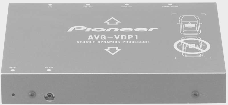
Because of the way the RPM detection
works in the AVG-VDP1, I added a device that
provides the proper signal.
In order to
install this system cleanly, I spent several
hours mapping out the circuit diagram.
It took another couple hours creating
all the wiring leads with connectors.
I cut a board
to fit in the rear compartment of the car
and reinforced the border with angled
aluminum so that the board would not warp,
and so it would be raised off the floor of
the compartment to help with cooling.
All of these
preparations took the better part of four
weekends, working around my family schedule.
I would like to emphasize how critical it is
to approach an installation like this in an
orderly fashion. In the final stages
of assembly and connection, you want to be
sure all sub-assemblies are clearly
documented, all wiring follows the color
coding of the main components (without
exception) and all connections are solid
and transmit a signal. Troubleshooting
something of this complexity without meeting
these considerations would be a nightmare.
If you don't have enough red
wire, go get some - don't just use black because you have
it! You will regret it later!
RPM Detection
The Chrysler
Crossfire (and Mercedes SLK that this car is
underneath the body-skin) have High
Energy Ignition (HEI) systems. The
power for spark is sent from the fuse panel
to individual coil packs at each cylinder.
These in turn fire two spark plugs per
cylinder. The good news is that this
makes for very clean operation.
Mercedes includes a very sophisticated noise
suppression circuit to make sure none of the
ignition noise reaches the car sound system.
It's so good in fact that the Pioneer
AVG-VDP1 when wired in normal manner, does
not detect the signal needed to calibrate
RPMs. Consequently the unit is more or
less useless. I found that if I wire
an additional device (the MSD GMR Pickup) I
can get the signal I need for the proper
operation of the AVG-VDP1. This meant
wiring the MSD into the loop and attaching
it to one of the coil packs. The
12-volt output from the MSD takes the place
of the switched 12-volt lead making it a
different source for this connection than
the AVD-W6210.
Hand Brake Signal
I have found
the operation of my GPS in my Jeep Commander
to be very frustrating because when the
vehicle is in motion, most features are
disabled. Not even the front seat
passenger can load and search a destination
on the GPS if the car is moving. It's proven to
be a huge pain. With this unit, I
didn't want to be stuck pulling the
handbrake to gain the use of many of the
functions of the Pioneer AVG-VDP1.
While it is true that it's a bad idea to get
involved operating electronic devices while
driving, some of the things that are
disabled don't require much attention.
So instead of wiring the brake signal lead
to the parking brake, I wired it to a toggle
switch that I can turn on and off to
simulate the use of the hand brake.
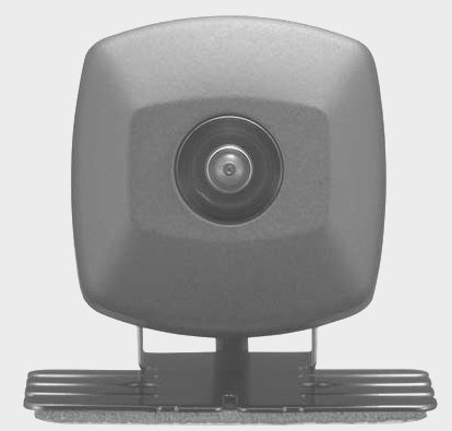
Rear-View Camera
The
rear-view camera comes on automatically when the car is put in
reverse gear and the reverse lights come on. But I wanted
to take it one step further and have the rear-view camera
available on demand without putting the car in reverse.
The rear view is not that great so there are times when being
able to see better out the back comes in handy, and it's not
always when the car is in reverse. When I connected the
switch to the reverse signal lead on the barrier strip, the
camera only came on when I put the car in reverse. I
checked the leads and power from the switch I installed and
everything seemed OK. I could not figure out why the
switch would not activate the camera, but reasoned that perhaps
something was going on to cause a side-effect. I added
diodes so the switch and reverse lights would not "know" about
each other, and this cured the problem. When either the
reverse lamps come on (the car is in reverse) or the switch is
activated (or both), the camera comes on and provides a
rear-view. Just what the doctor ordered.
Switches and Relay
I chose illuminated switches
to simulate the hand-brake and reverse signals. The switch is made
to control the 12-volt lead and has a simple
design that turns on the illumination when
12-volts flows through it. The problem
was that I needed to close a circuit to
ground which meant that if I wired the
switch to do what I wanted, the switch would
not light up when I turned it on.
So I
added a relay to the circuit. The
switch sends 12-volts to the relay and
lights up. The relay closes the ground
lead and "tells" the AVG-VDP1 that the hand
brake is "ON". A long way to go for a
lit switch but that's what I wanted so this
is how I achieved it. Here's a
detailed view of the relay connections for
the fuse panel.
Note that the relay
for the hand brake signal has terminals 30
and 87 closing the path to ground (-) rather
than to power because the AVG-VDP1 is
looking for ground on this wire rather than
12-volts. That's why the switch alone
would not work. The circuit for the
reverse signal is a straight switch that transfers a 12-volt
signal to the component "telling" it that the car is in reverse
gear - for the purpose of manually activating the rear-view
camera (installed separately).
See also
http://www.bcae1.com/relays.htm and
http://www.the12volt.com/relays/relays.asp
Bosch Relay Guide (PDF)
Reverse Signal
To allow manual
control of the rear-view camera, enabling rear-viewing even when
the car is not in reverse, I installed a switch to activate the camera on demand.
This left me with two switches to wire and
locate in the car.
Wire Loom Junction
To reduce the
number of wires that I had to run and
conceal, I decided to use a junction panel,
or "barrier strip". Both the AVG-VDP1
and AVD-W6210 share some leads that both
connect to the same endpoints.
These are the
Battery (12-volt +), Hand Brake signal
(Ground), Back Up Signal (12-volt power when
reverse is engaged), and Ground (-).
The AVG-VDP1
has two leads that are unique to it (the
Switched 12-volt lead that I am using to
carry the RPM signal) and the Speed Signal
lead.
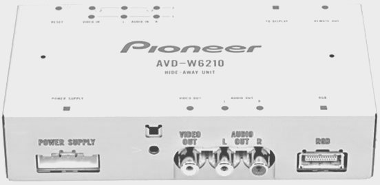
The AVD-W6210
uses a more conventional switched 12-volt
(+) lead).
This left me
with six (6) unique signals. By using
the switched 12-volt lead to feed my
illuminated switch, I came up with a seventh
signal.
I used an
8-position barrier strip to act as a
junction for these connections. On the
inbound side there are four (4) junctions
that each have two leads. The other
three (3) have single connections. On
the outbound side (to the car), each
terminal has a single lead. This gives
me a place to merge down the redundant
leads, and to have a manageable splice point
for these wires.
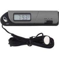
Cooling and Monitoring
Realizing the
compartment with the components will get
warm, I installed a small indoor/outdoor
thermometer that gives me the temperature
inside the cabinet, and in the car.
This allows me to monitor the temperature.
Since the wire was not long enough to reach
the dash and be concealed, I placed the
thermometer inside the console compartment
where I can refer to it as needed. The
side bonus is that the console compartment
contains the iPod so I can see if things are
getting too hot there as well. It's
all good...
After monitoring temperatures in
the compartment I found that the units do not produce much heat.
The temperature inside the compartment is only a couple degrees
higher than the temperature outside the compartment.
Still, in the dead of summer when the sun hits the black carpet
through the big hatch window, I am sure there will be plenty of
heat and some air flow will be necessary to preserve the life
and reliability of these electronics.
To keep the
components cool, I added a few vents on the
enclosure and installed a cabinet fan.
To control the fan I added a thermal switch
that comes on at 115 degrees and shuts off
at 90 degrees. I added a warning light to inform
me that the compartment is above 115 and that the fan is
(supposed to be) on. This gives a fan
that self regulates and a monitoring indicator to let me know
when it's coming on. A quick test of the completed circuit
using the bottom of a cup of hot coffee to activate the switch
confirmed that it comes on and shuts off in the desired
temperature range.
Fuse Panels
Since this
subsystem has so many elements, I decided to
incorporate another pair of fuse boxes.
One fuse box takes a 12-volt (+) feed from
the battery with a 30-amp circuit breaker providing
protection between the battery and the
firewall. This lead supplies the power
to the "un-switched" fuse panel.
This power is
fed through another relay that is activated
by the same factory-original fuse panel feed
that is activated by the key (and controls
the stereo). When the key is turned
on, the 12-volt signal activates the relay,
which makes the connection from the
un-switched fuse panel and provides power to
the "switched" fuse panel.
System Demarcation
In order to be
sure it would be easy to remove the
components as a single unit, without having
to disconnect any of the leads, I created a harness for the
leads that go to various parts of the car,
isolating the board and components so that
only the harness connector need be separated
to remove the entire unit in one piece. This is
necessary because the tire repair and
jacking equipment lie under the compartment.
It also makes sense from a design point of view. This way,
the valuable pieces can be isolated in event the car goes
someplace for service, or for when the car is sold.
I purchased an interlocking
connector with a few extra pins on it. This gives me some
expansion capability (for the rear view camera and ...?)